
|
Straight FAQ's on FEMA Surplus Civil Defense Meters with Retail and Wholesale Sources Listed! |
|
for Potassium Iodide (KI) tablets, Potasium Iodate (KIO3) pills, and all forms of radiation protection iodine! |
| ||||||
| App. E: How to Make a Homemade Piston Pump |
|


How to Make and Use a Homemade Plywood Double-Action Piston Pump
THE NEED
Ventilating pumps-mostly centrifugal blowers capable of operating against quite high resistance to airflow-are used to force outdoor air through most high-protection-factor fallout shelters and through almost all permanent blast shelters. Low-pressure ventilating devices, including ordinary bladed fans and homemade air pumps such as KAPs and Directional Fans, cannot force enough air through a permanent shelter's usual air-supply system consisting of pipes, or of pipes with a blast valve, a filter, and the valves needed to maintain a positive pressure within the shelter.
Manually cranked centrifugal blowers, or blowers that can either be powered by an electric motor or be hand-cranked, are the preferred means of ventilating permanent shelters from Switzerland to China. The main disadvantages of efficient centrifugal blowers are:
1. They are quite expensive. For example, in 1985 a good American hand-cranked blower, that pumps only about 50 cubic feet per minute (50 cfm) through a shelter's pipes, blast valve and filter, retails for around $250. An excellent foreign blower that enables one man to pump somewhat larger volumes sells for about twice as much.
2. Not enough centrifugal blowers could be manufactured quickly enough to equip all shelters likely to be built during a recognized crisis threatening nuclear attack, and lasting for weeks to several months.
Therefore, there is need for an efficient, manually operated, low- cost ventilating pump that:
3. Can pump adequate volumes of outdoor air through shelter- ventilating systems that have quite high resistances-up to several inches water gauge pressure differential.
4. Will be serviceable after at least several weeks of continuous use.
5. Can be built at low cost in home workshops by many Americans, using only materials available in most towns.
6. Could be made by the millions in thousands of shops all over the U.S., for mass production during a recognized prolonged crisis, using only plywood and other widely available materials.
To produce such a shelter ventilating pump, during the past 20 years I have worked intermittently designing and building several types of homemade air pumps. However, until I was traveling in China as an official guest in October 1982 and saw a wooden double- action piston pump being used, I did not conceive or come across a design that I was able to develop into a shelter-ventilating pump that meets all of the requirements outlined above. Now I have made and tested a simple homemade Plywood Double-Action Piston Pump, described below, that satisfies these requirements. Three other persons have used successively improved versions of these instructions to make this model, and several others have contributed improvements.
HOW A PLYWOOD DOUBLE-ACTION PISTON PUMP WORKS
Fig. 1 pictures the box-like test model described in these instructions.
Fig. 1. Plywood Double-Action Piston Pump, with manometer attached for tests. 
Fig. 2 illustrates a vertical section through a slightly improved model, and shows the 12x12-in. plywood piston being pushed from right to left, causing air from the outdoors to be "sucked" down the open air-supply duct in the top of the pump, then down to the right through the open valve in the airtight frame (that is above and near the right end of the PARTITION), and on down into the lower- pressure area behind the leftward-moving piston.
Because the air to the right of the leftward-moving piston is at a lower pressure than the air in the shelter room, the exhaust valves in the front end (the handle end) of the pump are held closed.
During this half of the pumping cycle, the higher-pressure air in the part of the pump's square "cylinder" to the left of the leftward-moving piston opens the air-exhaust valves in the back end of the pump, and fresh air is forced out into the shelter room, The higher-pressure air to the left of the valve in the airtight frame (that is above the left end of the PARTITION) keeps this valve closed, while the lower-pressure air to the right of this valve helps keep it closed.
When the piston is pulled to the right, all of the valves shown closed are quickly opened, and all shown open are quickly closed. Then fresh air is forced into the shelter room through the opened exhaust valves in the front end of the pump.
Fig. 2. Vertical Section of the Double-Action Piston Pump showing its square piston being pushed to the left. 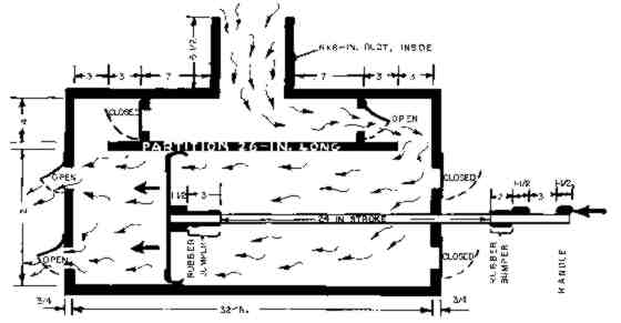
Book Page: 262
PERFORMANCE TESTS
The volumetric and durability tests summarized below are proof that this homemade Plywood Double-Action Piston Pump is better than most hand-cranked centrifugal blowers for supplying a shelter with outdoor air through typical air-intake and exhaust pipes- especially when the ventilation system contains a filter and/or blast valves. The filters that give the best protection, Chemical Biological Radiological (CBR) Filters, have quite high resistance to airflow, as do commercial blast valves that close quickly enough to protect filters.
1. Volumetric tests.
Because the rapidly pulsating airflows into and out of a piston pump are very hard to measure accurately with an air velocity meter, I made an inflatable cylindrical bag of 2-mil (0.002 inch) polyethylene film; the fully inflated volume of this bag was 256 cubic feet. The bag was suspended on a horizontal strong cord running through its length. A short tube 62 inches in circumference connected the back end of the pump (that is opposite the operator's end) to the suspended bag. Bag and pump were in a below ground shelter that normally has essentially motionless air. See Fig. 1.
Since this type of pump exhausts equal volumes of air from each of its two ends, the total cubic feet per minute (cfm) that it pumps equals twice the cfm that it exhausts into the shelter from one of its ends. See Fig. 1, that shows the pump attached with "C" clamps to a small steel table and being used to pump air into the 256 cubic foot suspended bag.
I measured the pressure differences against which the pump was operated. In a shelter these differences typically are caused by the resistance to airflow in pipes, valves, and a filter. I measured pressure differences in inches water gauge (1 in. w.g. 0.036 psi) with the small-tube manometer attached to the side of the pump. To produce various pressure differences for several tests, I nailed a piece of plywood over the top of the air-intake duct, so as to produce different sized openings: in most tests I placed different layers of filter materials in a filter box that was fitted airtight over the 6 x 6-in. air-supply duct on the top of the pump. See Fig. 3. (This low-resistance filter removes practically all fallout particles of wartime concern, and also most infective aerosols that may be used in biological warfare. See "Making and Using a Homemade Filter Box and Filter", by Cresson H. Kearny, October 1985.
Fig. 3. Pump with Homemade Filter (20 x 20 x 8-inches inside dimensions) connected airtight on top of the pump's 6 x 6-inch air-intake duct. 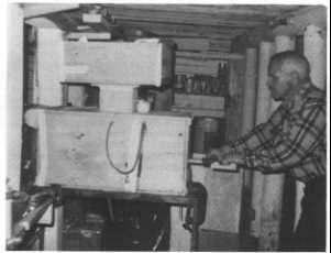
The best centrifugal blowers that I have seen or heard about are those manufactured by a Finnish company, Temet Oy. (I cranked a Temet Oy blower in an Israeli shelter used for testing ventilation equipment: the Finnish centrifugal blower was better than Swiss, German and captured Russian blowers also undergoing tests.) Therefore, in Table 1 a few of the volumetric tests of my best model Plywood Double-Action Piston Pump (powered by one and two men) are compared with performance data furnished by Temet Oy for its centrifugal blower when cranked by two men. I have converted Temet Oy's metric units into the common American units.
In Table 1 the pressure difference of 4.3 inches water gauge is the resistance to airflow that Temet Oy realistically gives as typical of a well designed shelter ventilation system of pipes, valves and blower plus a Chemical Biological Radiological (CBR) filter. Temet Oy gives 2.0 inches water gauge as typical of the same ventilation system with only a low resistance dust filter. The much larger volume pumped by the Double-Action Piston Pump when a CBR filter is used (as compared to the cfm pumped by this very good centrifugal blower) is typical of the reduced effectiveness of even the best centrifugal blowers at high pressure differences.
In areas devastated by a nuclear explosion, the typical very dusty conditions are likely to result in filters soon becoming dirty and higher in resistance to airflow. Then the greater effectiveness of a piston pump for ventilating a shelter with a high-resistance air-supply system will be even more important than when its filter is clean.

Table 1. Comparison of Plywood Double-Action Piston Pump with Temet Oy Centrifugal Blower.
| TYPE OF PUMP | PRES. DIFF (in. w.g.) | CUBIC FEET PER MINUTE
| HORSE-
|
| Double-Action | |||
| one man | 4.9 | 134 | ? |
| two men | 4.3 | 182 | ? |
| Temet Oy | |||
| two men | 4.3 | 90 | 0.15 |
| Double-Action | |||
| one man | 2.3 | 172 | ? |
| two men | 2.3 | 208 | ? |
| Temet Oy | |||
| two men | 2 | 300 | 0.18 |
The horsepower requirements of my pump have not yet been measured. However, based on the calculated air pressure on the 12 x 12-in. piston of 22.3 lbs. when the pressure difference was 4.3 in. w.g. (0.155 psi), when two pumpers were making 52 strokes (cycles) per minute while pumping 182 cfm, the horsepower delivered was about 0.14 HP without allowing for friction and the losses of power due to reversals in the directions of piston movements. I estimate that the actual horsepower delivered by the two pumpers (I, a 69 year old with a stiff back in 1983, and a 15-year-old boy) was somewhat less than 0.2 HP. A man in good condition can work for hours delivering 0.1 HP.
When comparing machines powered by human muscles, what muscles are used and how they are used are often as important as are the horsepower requirements. Leg muscles are more efficient and are much stronger than arm muscles. Arm muscles are used much more in cranking a blower than in pushing and pulling the piston of a properly designed reciprocating piston pump back and forth horizontally. See Fig. 3. If this double-action piston pump is placed at a height above the floor so that its handle is approximately at the height of a standing operator's elbows, then the operator can do most of the work with his legs. See Fig. 3. He efficiently moves his body back and forth for over a foot, while moving his hands and forearms horizontally for slightly less than a foot relative to his body. To deliver the same horsepower by cranking a blower uses less efficient muscles inefficiently, and is much more tiring.
As shown in Table 2, the volumetric efficiency of my best model is good for a shelter-ventilating pump. The volumetric efficiency of a piston pump (a positive displacement pump) is found by dividing the cfm actually pumped by the theoretical maximum cfm at the same pumping rate and the same pressure difference, assuming all piston strokes are full length, that all valves open and close instantaneously, and that there is no leakage. Table 2 shows that the greater the pressure difference, the lower the efficiency- as one would expect, because of increased leakage.
| PRES. DIFF (in. w.g.) | STROKES PER MINUTE | cfm | EFFICIENCY |
| 4 | 36 | 122 | 84.0% |
| 2.6 | 45 | 160 | 89.0% |
| 0.7 | 51 | 188 | 92.0% |
| 0.4 | 54 | 202 | 94.0% |
| 0.2 | 55 | 208 | 94.5% |
Table 2. Volumetric Efficiencies of Double-Action Piston Pump Operated by One Man.
Book Page: 263
2. Durability tests.
Finding a homemakeable method to seal the moving piston so as to assure at least one month of continuous efficient pumping was the most difficult problem. Various rubber seals attached to the edges of the piston were unsatisfactory, and aluminum sheetmetal strips (shaped and attached like the galvanized steel sheetmetal strips used in this model) wore out in less than a week, even when oiled every 24 hours.
To save money during weeks of continuous durability testing, the pump was operated by an electric motor that powered a pulley drive that turned a 2-foot-diameter pulley having an attached 40-in.-long steel pitman with a hinged connection to a horizontally- sliding bar connected to the handle of the pump's wooden piston rod. See Fig. 4.
After pumping for 380 hours (15.83 days) at 44 strokes per minute against a pressure difference of 2.3 in. w.g., the worst worn spot on any of the 30-gauge steel sheetmetal sealing strips on the piston was reduced in thickness from its original 0.0155 in. to 0.0145 in. This worst-spot wear of 0.001 in. is only about a 6% reduction in thickness. The flap valves functioned as well as when new, and appeared unworn.
I conclude that this pump would be serviceable after several months of continuous use-provided it is lubricated after every 24 hours of actual use, as in this durability test. In this test I lubricated the piston, its "cylinder's" four walls, and its rod with Lubriplate Ne. 105, "the original whito grease". This non-sticky "grease-type lubricant" is used extensively, especially to lubricate internal combustion engines before first starting up. Another builder of this model pump found Siloo White Lube, an all-purpose lithium grease, the best of the lubricants that he tested. Judging from my' prior durability' tests, a very' light oil applied daily serves reasonably well. Ordinary bearing grease is unsatisfactory.
MATERIALS
The following materials (that cost about $65. retail in 1985) are needed to make and operate the best model of this pump:
Plywood, 3/4-in. exterior: one 4 x 8-ft. sheet (finished on one side, unwarped).
Plywood, 3/8-in. exterior: 1/4th of a 4 x 8-ft. sheet (finished on one side, unwarped). (Second choice: 1/4-in. exterior plywood).
Oak board, 3/4 x 1-3/4 in., straight, well seasoned, 4 ft. long, to make the piston rod. (If oak or other very' strong wood is not available, use a straight fir or pine board.)
Fir or pine board, about 3/4 x 1-3/4 in., 8 ft. long, to make the piston-rod handle, etc.
28-gauge or lighter galvanized-steel flashing (sold by lumber yards for roofers), no thicker than 0.016 in.: or galvanized steel or flashing no thinner than 0.012 in. Or 30 gauge galvanized steel sheetmetal available in some sheetmetal shops. (Sheet- metal thicker than 0.016 is not springy enough for making this pump's near-equivalent of piston rings.) Best to go to a sheet- metal shop and have 3 strips cut, each 3 in. wide and about 30 in. long.
Screws, round-headed, zinc-plated wood screws:
22 each of No. 12 (2-in. long, 12/32 in. dia.), with flat washers 10 each of No. 10 (1-1/2 in. long, with flat washers)
15 each of No. 6 (3/4 in. long, with flat washers)
Nails, 4-penny (1-1/2 in.), best cement-coated: 1/4 lb. Nails, 3-penny (1-1/4 in:), galvanized: 1/4 lb.
Staples (if an oak board for the piston rod is not available), No. 17, 3/4-in., galvanized): 1/4 lb.
Tacks, No. 6 upholstery, (1/2-in. long): a small container. Tacks, No. 3 upholstery (3/8-in. long): a small container. Felt, weather stripping, 5/8-hi. wide: 10 ft.
Tape, silver duct tape, 2-in. wide: a small roll.
Tape, masking tape, 3/4-in. wide: a small roll.
Adhesive, waterproof: "Liquid Nails", or other all purpose construction adhesive: one approx. 11-oz. tube (for use in caulking gun).
Epoxy, 5-minute: 2 tubes.
Rubber cement: a small tube.
Sealer (such as polyurethane clear finish, to reduce absorption of oil or other lubricant of the "cylinder"): 1/2 pint.
Plastic film, transparent storm-window type (such as 4-mil Flexo-Glass, by Warp Bros.): 3 sq. ft.
Grease-type lubricant, an all-purpose motor-breakin lithium grease such as "Siloo White Lube" or "Lubriplate No. 5 Space Age Lubricant": two approx. 10 oz. tubes.
Inner tube rubber, heavy truck or auto (cut from an old tube): 1 sq. ft.
FUNCTIONAL RELATIONS OF PARTS
Look at Figs. 2, 5, and 6. In Figs. Sand 6, the lower, fixed part of the front end is pictured below the piston rod. The piston rod slides back and forth on the center of the fixed part of the front end (as indicated more clearly in Fig. 7), and in the notch in the removable part of the front end.
Fig. 4. Mechanized Drive Used in Weeks-Long Durability Tests. 
Fig. 5. Front End of the Durability Test Pump, showing the lower fixed part (below piston rod) and the upper removable part, that is held by 6 screws with flat washers. Felt weather-stripping makes the removable part airtight. 
Book Page: 264
Fig. 6. Pump Built by Dale Huber, of Lake City, Florida in his home workshop, while guided only by the second draft of these repeatedly improved instructions. The removable part of the front end has been taken off, to insert the piston into the 12 x 12-in. "cylinder" under the PARTITION. The plastic flaps of this pump's flap valves are black: transparent plastic film is preferred. 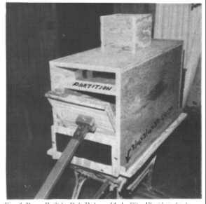
Note that a single plastic-film flap covers each pair of 2 x 4-in. valve holes, and that, as shown in Fig. 2 (that gives a side view of all six flaps), all flaps open away from the vertical center-plane of the pump.
In Fig. 5 the removable (upper) part of the front end is shown in place, secured by six round-head screws with flat washers. In Fig. 7 note the pair of 2 x 4-in. flap- valve holes above the piston rod.
In Fig. 6. the removable part of the front end has been removed, exposing the 26-in.-long, horizontal PARTITION that serves as the top of the 12 x 12-in. "cylinder", in which the piston can make a 24-in.-maximum- length stroke. Also see Figs. 2 and 7. Fig. 6 also shows the piston while it is being removed and one of the two rubber bumpers (made of inner tube rubber) on its piston rod.
The back end of the "box" is made of one piece of plywood, as shown in Fig. 8. The two plastic flaps of its exhaust valves each cover two 2 x 4-in. valve holes, that are positioned the same as the four valve holes in the front end.
Fig. 7. Front End (Operator's End) of Plywood Double-Action Piston Pump. The two 4 x 12-in. valve frames are shown by dashed lines, as is the 12 x 26-in. PARTITION. (tioned the same as the four valve holes in the front end. 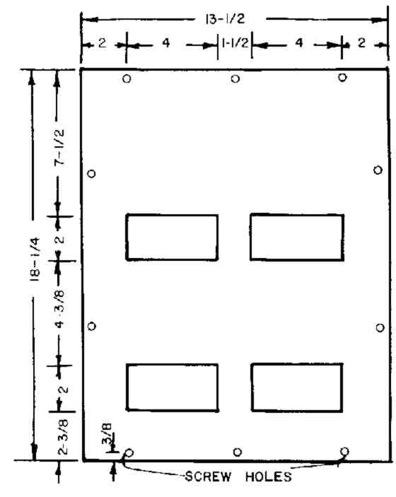
Fig. 8. Back End. Only the plywood is shown. 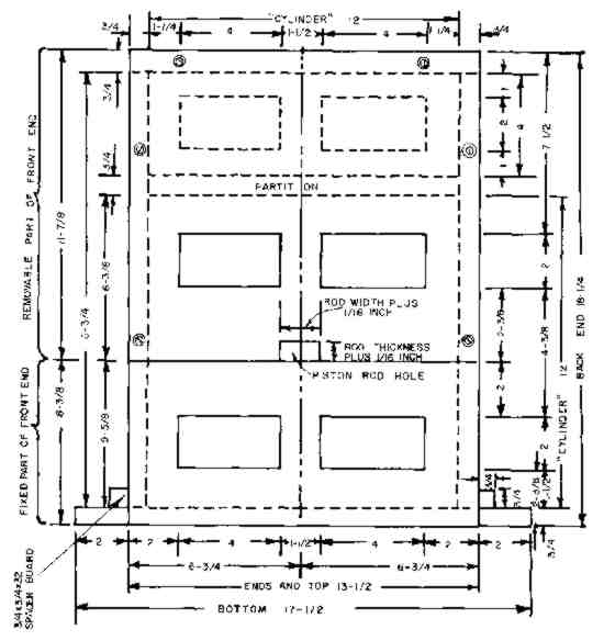
Book Page: 265
CUTTING OUT THE PLYWOOD PARTS
1. The four parts of the "cylinder" (its bottom, two sides, and the PARTITION: see Fig. 7) should be made with the wood grain of the plywood running in the same direction as the lengths of these parts. This reduces piston friction.
2. Outline on a sheet of exterior 3/4-in. plywood all of the plywood parts-except for the 12 x 12-in. piston and the two 12 x 12-in. construction forms, which are made of 3/8-in. exterior plywood. (If 3/8-in. plywood is not available, use 1/4-in.) Do not assume that the corners of a sheet of plywood are truly square. Also check the width of the sawcut of the saw to be used, and allow for this width when drawing adjacent outlines of parts on the plywood. Be sure to make all corners square.
3. If you do not have a table saw that saws accurately, or a heavy- duty' saber saw, you will do well to pay a professional carpenter or cabinet maker to saw out the plywood parts-and also the piston rod if you are making it out of an oak board. A professional can accurately saw out all of the plywood parts and the 10 valve holes in about 2 hours, provided you have accurately outlined all saw lines.
4. Make the following plywood rectangles with tolerances of + or - 1/32 in.:
PARTITION, 12 x 26-in.
Two sides, each 16-3/4 x 32-in. (If your "3/4-in. plywood" actually is less than 11/16-in. thick, make the height of each of your sides 16-3/4-in. less the difference between 3/4-in. and the actual thickness of your plywood. See Fig. 7.)
Bottom, 17-1/2 x 32-in.
Top, 13-1/2 x 32-in.
Two valve frames, each 4 x 12-in.
Piston, 12 x 12-in. (of 3/8-in. plywood).
Two construction forms, each 12 x 12-in. (of 3/8-in. plywood).
5. Make the following plywood rectangles with tolerances of + or - 1/16 in.:
Back end, 13-1/2 x 17-1/4-in. (See Fig. 8.)
Removable (upper) part of front end, 13-1/2 x 10-7/8 in. (See Figs. 7 and 9.)
Fixed (lower) part of front end, 13-1/2 x 6-3/8-in. (See Figs. 7 and 10.) The four parts of the air-intake duct: two each 6-1/2 x 6-in.; two each 6-1/2 x 7-1/2-in.
Two spacers (to be nailed to the bottom) each 3/4 x 3/4 x 32-in.
6. Saw out the 10 valve holes; a tolerance of + or - 1/8 in. is good enough. (See Figs. 7, 8, 9, and 10.)
7. Saw a square 6 x 6-in. hole in the center of the top, as shown in Fig. 2 - if you are going to install the homemade filter (described in separate instructions) directly on top of your pump. (To connect your pump to a round air-intake pipe, cut an appropriate round hole in the top.)
8. Sandpaper the finished sides of the PARTITION, the two sides, and the bottom, to reduce friction on the reciprocating piston. Use fine sandpaper.
9. Make and attach the 6 valve flaps, to complete the flap valves, that are the lowest resistance, quickest acting type tested.
a. Make a 3-3/4 x 5-3/4-in. cardboard TEMPLATE, using carbon paper to transfer lines of Fig. 11 to cardboard. (See Fig. 11 on page 7, and note that this TEMPLATE outlines the right half of the 3-3/4 x 11-1/2-in. plastic-film flap.) Also transfer the dashed tack-line and mark the ends of the 4 horizontal stop-string lines. Drill 8 small holes through the cardboard at the ends of the 4 stop-string lines, so that you can use a pencil to mark these points on plywood.
Fig. 9. Removable Part of Front End, Unfinished. Only the plywood is shown. 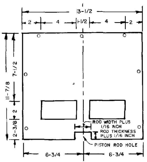
Fig. 10. Fixed Part of Front End, Unfinished. Only the plywood is shown. 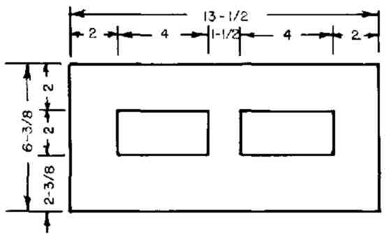
b. Use your TEMPLATE to mark around the 2 x 4-in. valve holes in plywood parts: (1) the positions of the ends of each hole's H stop- strings, (2) the right side-edge and the bottom-edge of each flap after it is attached, and (3) the tack-lines.
c. Drill a 1/16-in. diameter hole through the plywood at each point marked for an end of a stop-string.
d. With nylon kite string (or other nylon string about 1/16-in. in diameter, such as 50-lb-test nylon fishing line) and a big enough needle, string the "four" stop-strings across each 2 x 4-in. hole. (Use a string long enough to make "four" uncut stop-strings.) Start on the unfinished, back side of the plywood, on the opposite side from the future valve flap. To secure the starting end, wrap the string around a half-driven tack, and then drive it in. Keep pulling the string tight as you thread it through the holes and as you wrap its finishing end around a half-driven tack. Finally epoxy the string in all of the holes, on the back side of the plywood. (An equally strong nylon string can be made by twisting together 4 pieces of waxed nylon dental floss.)
(Stop-strings also can be positioned by using No. 3 upholstery tacks in place of the 1/16-in. diameter holes. Drive a tack partly' in, wind the string around it while pulling the string tight, and drive the tack completely in, to hold the string securely. Finally, coat the tack heads and the adjacent plywood with a smooth covering of adhesive, to provide a smooth seat for the valve flap.)
e. Cut out 6 plastic flaps of transparent 4-mil plastic film (each 3-3/4 x 11-1/2 in.). The easiest way to accurately' cut a flap of thin plastic film is to make a cardboard template 3-3/4 x 11-1/2-in.. place it on the film, and cut around it with a very sharp knife.
f. In preparation for attaching a flap over each pair of 2 x 4-in. valve holes, cover the plywood above each pair of holes with masking tape, up to the straight "tack line" that you already have drawn 1/2 in. above each hole. Use your cardboard TEMPLATE. The masking tape will prevent the adhesive (that will be used to attach each valve flap) from being applied too near the 2 x 4-in. holes, where adhesive would keep a flap from opening fully.
g. Position each of the 6 flaps properly' in its closed position, with its lower edge on the line that you already have used the TEMPLATE to draw 3/4 in. below each flap's pair of 2 x 4-in. holes. Position its right side-edge on the line already drawn 1 in. from the right side of the right hole of each pair of 2 x 4-in. holes. Then put masking tape over the lower edge of each flap and the adjacent plywood, to hold the flap temporarily' in its closed position.
h. Gently fold down the upper part of each flap, so that the plywood above its pair of 2 x 4-in. holes is uncovered (except where you have placed the protective tape), and place small pieces of masking tape so as to hold each flap temporarily in this folded-down position.
i. Quickly apply a thin coat of all-purpose construction adhesive (such as Liquid Nails) to a 1/2-in.-wide plywood area above the protective masking tape that covers the plywood up to the "tack line" 1/2 in. above each pair of 2 x 4-in. valve holes. Then promptly' detach the small pieces of masking tape holding the flap in its folded-down position, and turn the flap (the lower part of which is still being held in its proper closed position by masking tape) into the whole flap's closed position. Press the upper part firmly' against the approximately 1/2- in.-wide coating of adhesive, to secure the valve in its proper closed position. Allow several hours for the adhesive to harden before removing the tape and using the valve.
j. Drive small tacks (No. 3: 3/8 in.) on the "tack line" (see TEMPLATE), to make sure the flap stays securely attached after long use. (Very small tacks are easily driven if held with tweezers or needle-nosed pliers.)
Book Page: 266
PUTTING THE PUMP "BOX" TOGETHER
1. The following procedure is the best tested construction method for persons who lack experience in putting parts together so that all corners are exactly square, or who do not have the big clamps and other gluing equipment used by cabinet makers. This procedure is best carried out by two persons working together.
2. On the finished side of the top, draw two parallel lines exactly 12 in. apart and parallel to the top's 32-in.-long edges. Each of these lines will be 3/4-in. from an edge. Also draw a line 6 in. from and parallel to each end of the top, to mark the positions of the two valve frames. See Fig. 2.
3. Build the pump's "box" upside down; start by placing its top on the floor, as indicated by Fig. 12.
Fig. 12. Parts of the Pump "Box", with Dimensions in Inches. The Roman numbers give the best tested order for attaching these parts to each other. 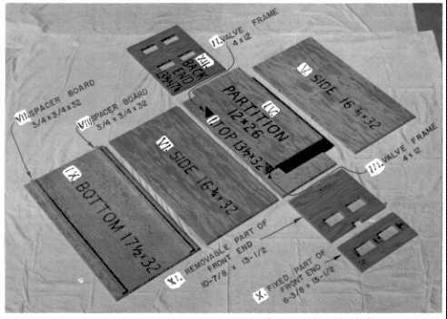
4. Attach the two valve frames II and III to the top I with construction adhesive, positioning each of them 6 in. from an end of the top I. Make sure that each frame's flap valve is upside down and facing away from the center of the pump. Remove any adhesive that is on the top beyond the ends of the valve frames.
(When using construction adhesive to make this pump, it is best to apply a rather thin coat to only one of the two plywood surfaces to be joined. Then promptly rub one plywood part slightly back and forth against the other, while pressing them together-thus making sure that both surfaces are coated and in close contact. Wait until the adhesive sets and bonds adequately before attaching more parts.)
5. Draw two parallel lines on the unfinished side of the PARTITION, each 3 inches from one of its ends. Adhere the two 12-in.-long unattached edges of the valve frames to the PARTITION on these two lines, as illustrated by Figs. 2, 7 and 12. Allow time for the adhesive to set.
6. Before permanently attaching side V, position it vertically with a long edge resting on the top, and with a side-edge of the PARTITION and ends of the two valve frames I and II in contact with the finished side of side V. See Fig, 7. On the unfinished (outer) side of side V draw lines showing the positions of the PARTITION and of the two valve frames in contact with the finished side of side V.
7. Preparatory to attaching side V to the PARTITION and to the two valve frames, drill 4 slightly oversize screw holes (for your 2-in. roundhead screws( through side V. Drill these holes so that a screw will go into an end of each valve frame about 1 in. from its adhered edge, and the other 2 screws will go into the side-edge of the PARTITION, at points above the valve frames. Next, with side V temporarily in its final position, drill with a smaller diameter drill through the 4 holes in side V, into the PARTITION and into the two valve frames. Then with the 4 screws temporarily connect side V, the PARTITION, and the two valve frames, and, while checking with a carpenter's square the squareness of the angle between the PARTITION and side V, adjust the two pairs of screws to attain squareness, Remove side V,
8. Apply adhesive to the 3/4-in.-wide area along the long edge of the top, and if necessary a thicker coating of adhesive than normal to unattached edges of the PARTITION and of the two valve frames. Then promptly position side V, and by again screwing in and adjusting the 4 screws, make the angle between the PARTITION and side V square. Allow the adhesive to set.
9. Use short pieces of duct tape to temporarily attach the two 12 x 12-in. construction forms to the PARTITION and to side V, (Before using these forms, drive 4 small nails into each form, near its corners, to serve as handles for removing them from the completed "cylinder".) Attach a construction form near each end of the PARTITION.
10. Adhere the finished side of side VI to the top, to the unattached side-edge of the PARTITION, and to end-edges of the valve frames, while keeping side VI pressed against the two square construction forms. To keep side VI pressed against the construction forms until the adhesive sets, use small nails to temporarily nail two small boards horizontally across the ends of the sides, at each end of the "box".
11. On the finished side of the bottom IX, draw two parallel lines 13- 1/2-in. apart, making each line 6-3/4-in. from the center line of the bottom, as shown in Fig, 7, Nail the two 3/4 x 3/4 x 32-in, spacer boards VII and VIII to the bottom, 13-1/2-in. apart.
12. To attach the bottom, first place it (with its finished side down) on the exposed long-edges of the sides, If you find that the bottom rests on the construction forms and is not in contact with the long-edges of the sides, in effect increase the heights of the sides by coating with adhesive both the edges of the sides and the 3/4-in.-wide area of the bottom to which the sides will be adhered, Then adhere the bottom onto the edges of the sides. Before the adhesive hardens, remove any that has been squeezed into the corner of the "cylinder".
Book Page: 268
. Permanently attach the fixed part of the front end X (see Fig. 7, 10 and 12) with adhesive and small nails to the sides and to the bottom. Be sure that its flap valve is upside down and is facing away from the center of the pump, and that a long edge of this part is level with the outer side of the bottom. Remove the construction forms.
14. Paint the interior of the "cylinder" with sealer-after removing all adhesive that may be in its corners.
15. After the sealer dries, sandpaper the interior of the "cylinder" with fine sandpaper, and paint it again with the final coat of sealer.
16. To attach the removable part of the front end XI, stand the "box" on its completely open end and drill slightly oversize screw holes (for your 2-in. screws) clear through the removable part of the front end, as indicated by Fig. 9. With the flap valve facing outward, temporarily attach this part with a few small nails to the end of the top and to ends of the two sides. Then with a smaller-diameter bit, drill the screw holes deep enough into the top and the sides so that the 7 screws will hold securely.
17. So that it will be unnecessary to tightly screw on the removable part of the front end in order to make its repeated temporary attachments airtight, tack felt weather-stripping (best 1/8-in. thick and 5/8-in. wide), or strips made of two thicknesses of flannel, to the contact edges of the top and the sides. No. 3 (3/8-in.) carpet tacks serve well. Then with a razor blade carefully cut the felt covering the screw holes in the edges, and remove these small pieces of covering felt.
18. Attach with screws the removable part of the front end.
19. To prevent damage to the front-end valve flaps when you stand the pump on its front end, epoxy a small piece of 3/8-in. plywood to the front end, near each of its four corners, as pictured in Figs. 3 and 5. Before standing the pump on its front end, use small pieces of masking tape to temporarily secure its valve flaps in their closed positions.
20. Attach the back end XII, using only screws. See Fig. 8. (For repairs, the back end may have to be removed.) To make the attachment of the back end airtight, coat its attachment "crack" only with rubber cement.
MAKING THE PISTON, THE PISTON ROD, AND ITS HANDLE
1. Have a sheetmetal shop cut three 3-ft.-long, 3-in.-wide strips of galvanized steel sheetmetal that is no more than 0.016-in., thick and no less than 0.012-in. thick. (Most galvanized steel valley flashing used by roofers and sold by many lumber yards is less than 0.016-in. thick; 30-gauge galvanized sheet metal sold by some sheetmetal shops is about 0.015-in. thick.) Steel sheetmetal thicker than about 0.016 in. is not springy enough and is unsatisfactory.
2. With a tolerance of + or - 1/32-in., cut from these strips two strips each 11-13/16-in. long, and two strips each 11-3/4-in. long. (These four strips first must be bent and then tacked to the four sides of the plywood piston; these piston-sealing strips serve rather like piston rings, by making close, sliding, low-friction contact with the sides of the plywood "cylinder". Steel strips resist wear and if properly lubricated make the pump serviceable for months of continuous use.)
3. Preparing the four sheetmetal sealing strips:
a. Since the strips to be tacked to the top and the bottom of the piston must be bent differently from the strips to be tacked to its two sides, mark "T or B" on each of he two strips that are 11-13/16 in. long, and mark "8" on each of the two strips that are 11-3/4 in. long.
b. On each of the two strips marked "T or B", draw an ink line along which to make the approximately 30 degree bend, and another line for the approximately 90 degree bend. (See the left half of Fig. 13 for the distances from the edges of these two "T or B" strips to their bends.) Also draw two ink lines along which to drive tacks, spaced as shown in the left half of Fig. 13.
Likewise draw four lines on each of the two strips marked "8", as specified in the right half of Fig. 13, noting that some of these lines are spaced differently than corresponding lines on the strips marked "Tor B"
c. Using a small sharpened nail for a punch and placing one strip of sheetmetal at a time on a smooth board, punch 2 rows of tack holes in each strip. The tack holes should be about 1-1/2 in. apart.
d. From a nominal 1 x 2-in. straight board, make two boards each about 3/4 x 7/8 x 12-1/4 in., for use in bending the sealing strips.
e. Securely sandwich a "T or B" strip of sheetmetal between the two 12-1/4-in.-long boards placed exactly on top of each other, by tightening two "C" clamps on the ends of the two boards, so that the bending line 3/8-in, from one side of the strip is just visible along the straight edge of a board. Then hold the two clamped boards in a vise so that the 3/8-in.-wide part of the sheetmetal strip is uppermost and vertical.
f. Bend the exposed part of the strip about 30 degrees off the vertical, away from the side of the strip where the holes have been indented by the punch. To bend evenly, hammer gently and repeatedly on a 3/4 x 3/4 x 18-in. board held against the exposed 3/8-in.-wide part of the strip.
Fig. 13.Piston Sealing Strips, each made of a springy sheetmetal strip 3 in. wide. 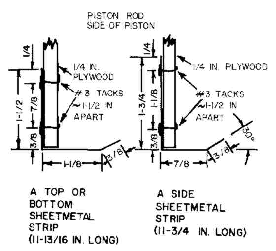
g. With the sheetmetal strip held sandwiched between the two 12-1/4-in.-long boards by the two "C" clamps and the vise, so that the bending line for the almost 90-degree bend is barely visible, bend the exposed part of the strip 90 degrees, in the same direction that the 3/8-in.-wide part was bent. See Figs. 13 and 14.
h. Bend the other "T or B" strip, and similarly bend each of the two "8" strips.
4. Attach the four sheetmetal sealing strips to the plywood piston with No. 6 tacks (1/2-in. long). Place on a solid metal surface the part of the plywood piston opposite the spot to which part of a strip is being tacked, so that when a tack is hammered in its point is clinched (bent over) on the far side of the 3/8-in.-thick plywood piston, by being hammered against the solid metal surface.
a. First tack a "T or B" sheetmetal strip to the top of the piston, and a "T or B" strip to its bottom.
b. Then tack the two "8" strips to its sides. The strips should fit together so as to make square corners. If adjacent ends of two strips do not fit neatly together, cut bit by bit a very little off the end(s) of a strip(s) so that the two adjacent ends fit together neatly at their
c. To prevent air leakage between the ends of the sealing strips, put rubber cement in the four corner "cracks" between strips. (This was not done on the test pump's piston.)
Fig. 14. Plywood Piston with Sheetmetal Sealing Strips Attached. 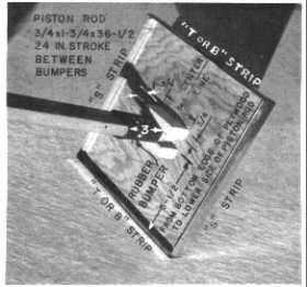
Book Page: 269
5. For the piston rod, saw from a straight, well-seasoned oak board a 3/4 x 1-3/4 x 36-1/2-in. board. Sandpaper it smooth. (A piston rod made of well-seasoned oak is less likely to break if abused, but necessitates using screws, in place of nails and staples, for attachments. Piston rods made of nominal 1 x 2-in. fir boards were undamaged in the tests.)
6. To complete the piston rod:
a. For the handle, use 4 pieces of a nominal 1 x 2-in. board cut to the lengths shown in Fig. 15. Also see Fig. 16. Round all edges and corners, to minimize the chances of the operators' blistering their hands.
b. Paint the piston rod and its handle with sealer. When dry, sandpaper. Then apply a final coat of sealer.
c. Use adhesive, screws, and nails (or adhesive and nails if your piston rod is of soft wood) in making the handle illustrated by Fig. 15
Fig. 15. Piston Rod Handle Made of 3/4 x 1-3/4-in. Boards. 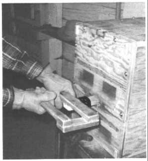
Fig. 16. The Pump Handle of the Durability-Test Pump, showing how one man best holds it when two men are pumping. 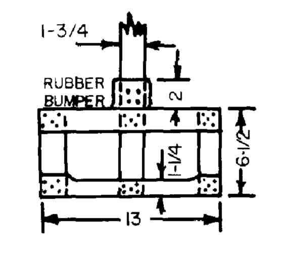
d. To reduce friction on the piston rod and resultant enlargement of the piston-rod hole with long use, coat with epoxy all four sides of the piston-rod hole. SeeFigs. 7 and 16. Be sure that the piston rod slides snugly yet freely in its hole when the removable part of the front end is screwed in place.
e. From a piece of thick truck-tire inner-tube rubber, cut a 2-in.- wide strip 12-in. long. To make the 2-in.-wide rubber bumper (see Figs. 15 and 16), connect one end of this rubber strip to the center of a 3/4-in.-wide side of the piston rod. Do not place any screw or staple in the strip closer than 1 in. from the strip's forward edge, that may repeatedly bump into the front end. Wrap and attach the strip quite tightly around the piston rod next to the handle. (If you have only a piece of passenger-car inner-tube rubber, then to make a 2-in.-wide bumper use a 4-in.-wide strip of this thinner rubber folded double lengthwise.)
7. Attaching the piston rod to the piston:
a. On the back of the 12 x 12-in. plywood piston, mark lines to enable you to attach the piston rod as pictured in Fig. 14. Note that the lower side of the piston rod is exactly 5-1/2 in. above the lower edge of the plywood of the piston, and that the center line of the piston rod intersects the vertical center line of the plywood of the piston.
b. To the end of the piston rod (see Fig. 14) adhere and screw (or adhere and nail if your piston rod is not oak) two pieces of nominal 1 x 2-in. boards each 3 in. long. Each of these two small boards and the end of the piston rod are in contact with and securely connected to the plywood piston, and form a perfect "T" at the end of the piston rod.
c. Connect the piston rod to the piston, best with epoxy (or adhesive) and small screws. Make sure that: (1) the four piston sealing strips overlap the piston's plywood in the direction of the piston rod, (2) the 1-3/4-in.-wide sides of the piston rod are parallel to the top and bottom of the piston, and (3) the piston rod is perpendicular to the piston. See Figs. 2 and 14.
d. Make and attach to the piston rod a 3-in.-long rubber bumper, positioned close to the piston as shown in Fig. 2.

OPERATING THE PUMP
1. Check to see that the four sheetmetal strips on the four sides of the piston all make even contact with the walls of the "cylinder" when the piston is moved back and forth. If the piston does not slide back and forth quite easily even when not lubricated, carefully bend a strip or strips so that they press less against the "cylinder" walls. If while someone is shining a flashlight through a valve opening in the other end of the pump you observe that parts of a sheetmetal strip do not make close contact with a "cylinder" wall, gently bend outward that part of the strip.
2. Lubricate all four walls of the "cylinder", the sheetmetal strips that slide against the walls, and the piston rod. Use a very thin motor-breakin white lithium grease (not an ordinary bearing grease, that is too sticky). Or use a thin oil. The pump should be lubricated after no more than each 24 hours of use, and before being used again after days of disuse.
3. Install the pump at a height above the floor so that most of the persons who are going to pump can push and pull with their hands moving at about the same height that their elbows are when they are standing. See Fig. 3for an example of a pump-supporting table raised to an efficient height for operators who are the height of the pumper pictured.
4. To save work and to minimize wear on the pump, usually operate it with a length of stroke a little shorter than the distance between its two rubber bumpers. To save energy especially when pumping air through ahigh resistance ventilation system, move the piston back and forth by using mostly your leg and body muscles.
PROLONGED STORAGE
Wipe off all grease and other lubricants if you do not plan to use this pump for months. All lubricants-especially those on wood-tend to become gummy with time.
Keepyour supply of pump lubricants taped to your pump.
REQUEST
Suggestions for improving this pump and/or these instructions will be appreciated, and may contribute to improvements likely to save lives.
Cresson H. Kearny
Copyright © 1986 by Cresson H. Kearny
No part of this work (except brief passages that a reviewer may quote in a review) may be reproduced in any form unless the reproduction includes the following statement: "Copyright © 1986 by Cresson H. Kearny. All or part of this information on the Plywood Double-Action Piston Pump may be reproduced without obtaining permission from anyone."
Book Page: 270
FILTER BOX AND FILTER
PURPOSES
The primary shelter ventilation requirement is to supply enough outdoor air to maintain endurable heat-humidity conditions.
To keep the concentration of respiratory carbon dioxide low enough for survival, very little fresh outdoor air is required. Evenfor an infant or an infirm person remaining in a crowded shelter for days, 3 cubic feet per minute (3 cfm) is adequate. For a healthy adult or child 1.5 cfm is enough. Too much carbon dioxide, not too little oxygen, is the initial cause of unendurable conditions in inadequately ventilated shelters in which the air does not get unendurably hot.
In contrast, up to 25 cfm of outdoor air per occupant may be needed to maintain endurable heat-humidity conditions inside a crowded shelter occupied for days during a heat wave in a hot, humid part of the U.S. Hence the need for a large-volume ventilating pump, best with a low-resistance filter.
If outdoor air flows into a shelter through a hood, gooseneck pipe, or other air-supply opening that causes all but tiny fallout particles to fall out before the air reaches shelter occupants, breathing this unfiltered air will not result in short-term radiation casualties. However, a very small fraction of the occupants of a shelter supplied with unfiltered air in an area of heavy fallout may contract cancer years later as a result of breathing shelter air containing tiny fallout particles, that a properly designed filter could have removed.
Air that has been in contact with fallout particles before being filtered is not radioactive,
The homemade filter illustrated below, if used with an efficient "suction" pump such as the Plywood Double-Action Piston Pump described separately, will remove practically all fallout particles likely to cause casualties even decades later, This filter also will remove most infective aerosols, the air-borne tiny particles used in biological warfare - an unlikely type of attack on the United States. It will not remove poisonous gasses, an even less likely danger to Americans if all-out war befalls us.
CONSTRUCTION
Filter Box
If 20 x 20-inch furnace filters are available, use plywood or boards to build the filter box shown in the illustration. To make permanent connections airtight, first use waterproof construction adhesive or glue, and then tape. (If only smaller filters are available, reduce the horizontal dimensions of the box accordingly, except for the top and bottom openings.) Check to be sure that your filters will fit snugly in the box of the size you plan to build.
The square frame on the bottom of the filter box should fit snugly over the square air-intake duct on the top of your Plywood Double-Action Piston Pump. Tape the cracks to make the connection airtight and to permit easy removal of the filter box.
Make the illustrated 4 supports of the hardware cloth no thicker than 3/4 inch, thus providing enough space below the filter for low- resistance airflow. (Hardware cloth is a stiff, square-mesh, molten- dipped galvanized wire.)
Make the square top of the filter box so that it covers the upper edges of the box's sides and can be easily removed. Then cut in its center a round hole slightly smaller than 4 inches in diameter. File the hole's edges so that a 4-inch-diameter can (such as a coffee can with its top and bottom cut out) fits snugly in this hole. To connect the can securely and airtight, first use waterproof construction adhesive or epoxy, and then tape. (If construction adhesive or epoxy is not available, cut a 2-1/2-inch-diameter hole in the center of the bottom of the 4-inch-diameter can. Then make radial cuts spaced about one-half inch apart, out to the full diameter of the can. Bend these tabs outward 180 degrees, preparatory to tacking them with small tacks to the bottom of the filter box top. Tape airtight.)
So that the top of the filter box can be easily removed, tape it onto its box. A roll of duct tape should be kept with the filter box and pump at all times.
To connect the filter box to the shelter's air-intake pipe, the best widely available air duct is the inexpensive, 4-inch-diameter flexible duct used with clothes dryers.
(Figure p.270) Homemade Filter To Fit On Plywood Double-Action Piston Pump, and To Be Connected to a 4-Inch-Diameter Air-Intake Pipe. 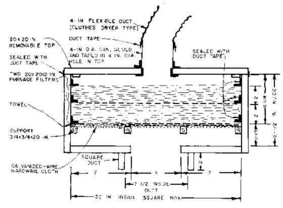
Book Page: 271
Filter Materials
Furnace or air-conditioner dust filters, those made of oiled fiberglass fibers, will remove practically all but the very smallest fallout particles. Filters that are sold in box-like housings can easily be installed so that all the pumped air will pass through them, by taping them to the inner sides of the filter box. The illustration shows two plain mats of furnace filter material, each taped around its edges. (If commercial dust filters are not available, bath towel cloth will serve. However, in very dusty areas a cloth filter may become overloaded, thus seriously reducing the rate of airflow much sooner than if an oiled fiber filter is used as a prefilter.)
To filter out most of the tiny particles that may pass through one or more furnace filters, place two thicknesses of bath towel on top of the filter-support made of hardware cloth, and tape them around their edges to the box. See illustration.
Tests by U.S. Army specialists have shown that filtering air through two thicknesses of bath towel removes about 85 percent of even microscopic aerosols as small as 1 to 5 microns in diameter. (See "Emergency Respiratory Protection Against Radiological and Biological Aerosols", by II. G. Guyton et al., A.M.A. Archives of Industrial Health, Vol. 20, July through Dec. 1959.) This is the size of most infective aerosols used in biological warfare. In most of an area subjected to a biological attack, if 85 percent of this size-range of infective aerosols and practically all larger particles are removed, then most persons breathing this filtered air will not receive enough infective agents to infect and sicken them.
Persons who are especially desirous of protecting their shelter's occupants against biological warfare aerosols, but who can not afford or obtain expensive High Efficiency Particulate Air filters (HE PA filters), should consider using disposable pleated air filters that meet official ASHRAE standards. One 2-in. pleated air filter, measuring 19-1/2 x 19-1/2 in., will remove over 90 percent of particles in the 1.0-5.0 micron range, yet when clean its resistance to an airflow of 200 cfm is only about 0.2 in. water gauge (about 0.007 psi). Its cost is about twice that of a good ordinary furnace filter of the same size. However, it has approximately three times the life of a standard panel type filter before becoming overloaded. Disposable pleated air filters are available in larger cities.
USE
The illustrated homemade filter has such low resistance to airflow that, when up to about 200 cfm is being pumped through it by a Plywood Double-Action Piston Pump, the air volume is decreased by only about 10 percent, as compared to the volume pumped with no filter in the ventilation system. With a homemade Plywood Double- Action Piston Pump, up to approximately 200 cfm can be pumped through this filter even when the total difference in air pressure (caused by the ventilation pipes, a dirty filter, etc. that restrict airflow) is high, about 5 inches water gauge (0.18 psi).
Even if the United States suffers an all-out Soviet attack, only a small part of its area will be subjected to blast effects severe enough to injure the occupants of fallout shelters. (Fallout shelters are not designed to withstand blast, but especially typical earth-covered ones afford consequential blast protection.) In contrast, an installed filter, unless protected by an efficient blast valve, will be wrecked by a quite low-pressure blast wave that comes down its open air-intake pipe -even if the small part of the blast wave that would enter the shelter room through its open ventilation pipes is not nearly powerful enough to injure the shelter occupants. Thus unprotected installed filters will be wrecked in an area several times as large as the area in which occupants of fallout shelters will be injured by blast.
To be sure of having a filter in good condition, you can:
1. Make and keep in your shelter an extra complete filter, ready to replace your installed filter if it is damaged, or if it becomes overloaded with dust and its resistance to airflow becomes too high. Furthermore, if your filter is installed in your shelter room and becomes so radioactive with retained fallout particles that it is delivering a consequential radiation dose to shelter occupants, it is advantageous to be able to remove it, pitch it out, and install a replacement filter. (To be able to supply your shelter with unfiltered air in peacetime or after the end of consequential fallout danger, you should make and keep ready a duct with appropriate fittings to connect your pump directly to its air-intake pipe.)
2. If you have only one filter, do not install it before you need to filter the air supply. Connect your pump directly to the air-intake pipe, using an appropriate duct and fittings. Then before the attack and before the arrival of fallout (revealed by your fallout-monitoring instrument), keep your shelter well ventilated with unfiltered air. Whether or not your filter is installed, stop ventilating your shelter for a few hours while heavy fallout is being deposited outside - unless heat-humidity conditions become unbearable. If before shelter ventilation is stopped the shelter air does not contain an abnormally high concentration of carbon dioxide, then no outdoor air need be supplied for about 5 hours to prevent building up too high a concentration of respiratory carbon dioxide - provided there is about 70 cubic feet of shelter-room volume for each occupant.
AN ENCOURAGING REMINDER
Persons making preparations to improve their chances of surviving an all-out attack should realize that if the United States is hit with warheads the sizes of those in the 1987 Soviet intercontinental arsenal, the fallout particles of critical concern will be much larger than the extremely small particles (1 to 5 microns in diameter) which are not completely removed by this filter. Fallout particles this small produced by large nuclear explosions do not fall to the ground for many days to months after the nuclear explosions, by which time they have become much less radioactive. Essentially all of the larger particles can be removed merely by filtering the air through a few thicknesses of bath towel cloth.
Book Page: 273
| |
|
compared for Potassium Iodide (KI) tablets, Potasium Iodate (KIO3) pills, and all forms of protective iodine! |