|
Straight FAQ's on FEMA Surplus Civil Defense Meters with Retail and Wholesale Sources Listed! |
|
for Potassium Iodide (KI) tablets, Potasium Iodate (KIO3) pills, and all forms of protective iodine! |
| ||||||
| App. D: Expedient Blast Shelters |
|


|
Straight FAQ's on FEMA Surplus Civil Defense Meters with Retail and Wholesale Sources Listed! |
|
for Potassium Iodide (KI) tablets, Potasium Iodate (KIO3) pills, and all forms of protective iodine! |
| ||||||
| App. D: Expedient Blast Shelters |
|

INCREASING IMPORTANCE
The majority of urban and suburban Americans would need blast shelters to avoid death or injury if they did not evacuate before an all-out nuclear attack. As nuclear arsenals continue to grow, an increasing majority would need the protection of blast shelters. In an attack on militarily relevant targets, as much as 5% of the total area of the 48 states could be subjected to blast damage severe enough to destroy or damage homes depending on the number of warheads assigned to each hard target, weapon reliability, etc. If blast shelters affording protection up to the 15-pounds-per-square-inch (15 psi) overpressure range were available to everybody and were occupied at the time of attack, the great majority of the occupants would survive all blast, fire, and radiation effects in the blast areas subjected to less than 15-psi blast effects.
Fifteen-psi blast shelters will survive as close as about 1.5 miles from ground zero of a 1-megaton surface burst, and about 2.3 miles from ground zero or a 1-megaton air burst. Except in high-density urban areas where the air supply openings and exits of shelters are all too likely to be covered with blast-hurled debris, the area in which people inside good earth- covered 15-psi blast shelters would be killed would be only about 1/6th as large as the area in which most people sheltered in typical American homes probably would die from blast and fire effects alone.
Blast tests have indicated that the SmallPole Shelter (the most blast-resistant of the earth-covered expedient shelters described in Appendix A) should enable its occupants to survive up to the 50-psi overpressure range - if built with the blast-resistant and radiation- protective features described in following sections, and if located outside an urban area. Calculations show that this earth-covered expedient blast shelter also would give adequate protection at the 50-psi blast overpressure range against the intense initial nuclear radiation that is emitted from the fireball of a 1-megaton explosion. However, to make this shelter (see page 258) provide adequate protection against the even more intense initial nuclear radiation that would reach the 50-psi overpressure range from the fireball of a 500-kiloton or smaller explosion, it should have at least 6 feet of earth cover and additional cans of water should be kept ready to be placed in the horizontal parts of the entryways promptly after the shelter is occupied.
The life-saving potential of well designed, well built blast shelters is a demonstrated fact. Millions of Americans living in high-risk areas would be able to build expedient blast shelters within only a few days provided they were given field-tested instructions, had made some preparations before the crisis arose, had a few days of recognized warning, and during the crisis were motivated by the President. The following information is given in the hope of encouraging more Americans to make preparations for blast protection. Also, it may serve to increase the number who realize the need for permanent blast shelters in high-risk blast areas.
Some informed citizens particularly those who live near large cities or in their outer suburbs may choose to build earth-covered expedient blast shelters in their backyards, rather than to evacuate. Going into a strange area and trying to build or find good shelter and other essentials of life would entail risks that many people might hesitate to take, particularly if they live outside the probable areas of severe blast damage. For such citizens, the best decision might be to stay at home, build earth-covered expedient blast shelters, supply them with the essentials for long occupancy, and remain with their possessions.
The following descriptions of the characteristics and components of expedient blast shelters should enable many readers to use locally available materials to provide at least 15-psi blast protection. Pre-crisis preparations are essential, as well as the ability to work very hard for two to four days. (Field-tested instructions are not yet available; to date only workers who were supervised have built expedient blast shelters.5)
PRACTICALITY OF EXPEDIENT BLAST SHELTERS
At Hiroshima and Nagasaki, simple wood-framed shelters with about 3 feet of earth over wooden roofs were undamaged by blast effects in areas where substantial buildings were demolished.4
Book Page: 244
Figure D.1 shows a Hiroshima shelter that people with hand tools could build in a day, if poles or timber were available. This shelter withstood blast and fire at an overpressure range of about 65 psi. Its narrow room and a 3-foot-thick earth cover brought about effective earth arching; this kept its yielding wooden frame from being broken.
Fig. D. 1. A small, earth-covered backyard shelter with a crude wooden frame-undamaged, although only 300 yards from ground zero at Hiroshima. 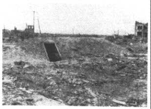
Although the shelter itself was undamaged, its occupants would have been fatally injured because the shelter had no blast door. The combined effect of blast waves, excessive pressure, blast wind, and burns from extremely hot dust blown into the shelter (the popcorning effect) and from the heated air would have killed the occupants. For people to survive in areas of severe blast, their shelters must have strong blast doors.
In nuclear weapons tests in the Nevada desert, box-like shelters built of lumber and covered with sandy earth were structurally undamaged by 10- to 15-psi blast effects. However, none had blast doors, so occupants of these open shelters would have been injured by blast effects and burned as a result of the popcorning effect. Furthermore, blast winds blew away much of the dry, sandy earth mounded over the shelters for shielding; this resulted in inadequate protection against fallout radiation.
Twelve different types of expedient shelters were blast-tested by Oak Ridge National Laboratory during three of Defense Nuclear Agency's blast tests.5 Two of these tests each involved the detonation of a million pounds or more of conventional explosive; air-blast effects equivalent to those from a 1-kiloton nuclear surface burst were produced by these chemical explosions.
Several of these shelters had expedient blast doors which were closed during the tests. Figure D.2 shows the undamaged interior of the best expedient blast shelter tested prior to 1978, an improved version of the Small-Pole Shelter described in Appendix A. Its two heavy plywood blast doors excluded practically all blast effects; the pressure inside rose only to 1.5 psi an overpressure not nearly high enough to break eardrums. The only damage was to the expedient shelter-ventilating pump (a KAP) in the stoop-in entryway. Two men worked about 5 minutes to replace the 4 flap-valves that were blown loose.
Fig. D.2. Undamaged interior of a Small-Pole Shelter after blast testing at the 53-psi overpressure range. Large buildings would have been completely demolished. 
Book Page: 245
When blast-tested at 5-psi overpressure, not even the weakest covered-trench shelters with unsupported earth walls (described in Appendix A) were damaged structurally. However, if the covering earth were sandy and dry and if it were exposed to the blast winds of a megaton explosion at the 5-psi overpressure range, so much earth would be blown away that the shelter would give insufficient protection against fallout radiation. Much of the dry, shielding earth mounded over some of the above- ground shelters was, in fact, removed by the blast winds of these relatively small test explosions, even at the lower overpressure ranges at which homes would be wrecked. In contrast, in blast tests where the steeply mounded earth was damp, little blast-wind erosion resulted. (The reader should remember that even if shelters without blast doors are undamaged, the occupants are likely to suffer injuries.)
CONSTRUCTION PRINCIPLES
Millions of Americans if given good instructions, strong motivation, and several days to work should be able to build blast shelters with materials found in many rural areas and suburban neighborhoods. During a crisis, yard trees could be cut down for poles and sticks, and a garage or part of a house could be torn down for lumber. Many average citizens could build expedient blast shelters if they learn to:
° Utilize earth arching by making a yielding shelter. The remarkable protection that earth arching gives to those parts of a shelter designed to use it is illustrated by Fig. D.3.
Fig. D.3. Effective earth arching in the earth covering of this 4-ft-wide Pole-Covered Trench Shelter prevented a single pole from being broken by blast forces that exerted a downward force of 53 psi (over 3-1/2 tons per square foot) on the overlying earth. 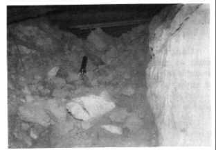
This picture shows the unbroken roof of a 4- foot-wide Pole-Covered Trench Shelter that was built in rock-like soil and blast tested where the blast pressure outside was 53 psi. Its strong blast doors prevented the blast wave from entering. Without the protection of earth arching that developed in the 5 feet of earth cover over the yielding roof poles, the poles would have been broken like straws. In contrast, the ground shock and earth pressure produced by 1-kiloton blast effects almost completely collapsed the unsupported, rock-like earth walls.
Fig. D.4. Post-blast interior of an Above- ground, Door-Covered Shelter that survived 1-kiloton blast effects at the 5.8-psi overpressure range. The shelter walls were made of bedsheets containing earth, as described in Appendix A. 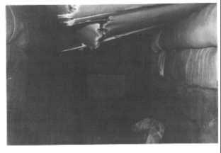
Figure D.4 also indicates the effectiveness of earth arching. This photo shows the roof of a small, earth-covered fallout shelter, as it appeared after surviving blast effects severe enough to demolish most homes. The roof was made of light, hollow-core, interior doors and looks as though it had been completely broken. In fact, only the lower sheets of 1/8-inch-thick veneer of the hollow-core interior doors were broken. (These breaks were caused by a faulty construction procedure a front- end loader had dumped several tons of earth onto the uncovered doors.) The upper 1/8-inch-thick sheets of veneer were bowed downward, unbroken, until an earth arch formed in the 2-foot-thick earth covering and prevented the thin sheets from being broken. Earth arching also prevented this roof from being smashed in by blast overpressure that exerted a pressure of 5.8 psi (835 pounds per square foot) on the surface of the earth mounded over this open shelter. (See Appendix A for details of construction.)
Book Page: 246
° Make shelters with the minimum practical ceiling height and width. Most of the narrow covered-trench shelters used by tens of thousands of Londoners during the World War II blitz were built with only 4-1/2 foot ceilings, to maximize blast protection and minimize high water-table problems. These shelters were found to be among the safest for protection against nearby explosions. The Chinese also have a good understanding of this 'design principle and skillfully utilize the protection provided by earth arching. A Chinese civil defense handbook states: '. .. the height and width of tunnel shelters should be kept to the minimum required to accommodate the sheltering requirements," and 'The thicker the protective layer of earth, the greater the ability to resist blast waves." 21
° Shore earth walls to prevent their caving in as a result of ground shock and earth pressure. Most unshored (that is, unsupported) earth walls are partially collapsed by ground shock at much lower blast overpressures than those at which a flexible roof protected by earth arching is damaged. Figure D.5 is a picture of a seated dummy taken by a high-speed movie camera mounted inside an unshored, Pole- Covered Trench Shelter of the Russian type tested at the 20-psi range. (A second dummy was obscured by blast-torn curtains made of blankets.) The shelter had an open stairway entryway, positioned at right angles to the stand-up-height trench and facing away from the targeted "city" so as to minimize the entry of blast waves and blast wind.
Fig. D.5. A dummy in an unshored Pole-Covered Trench Shelter as it is struck by collapsing rock-like earth walls. The photo also shows the shelter's blanket-curtains as they are torn and blown into the shelter by the 180-mph blast wind. (Immediately after this photo was taken, the dummies were hit by the airborne blast wave and blast wind. Outside, the blast wind peaked at about 490 mph.) 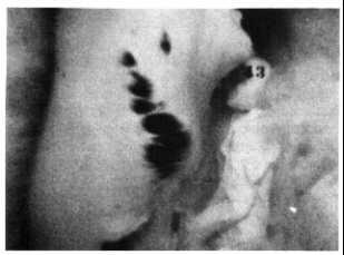
Figure D.6 is a post-blast view of the essentially undamaged earth-covered roof poles and the disastrously collapsed, unshored shelter walls of the Russian shelter tested at 20 psi.21 Russian civil defense books state that unshored fallout shelters do not survive closer to the blast than the 7-psi overpressure range. This limitation was confirmed by an identical shelter tested at 7 psi; parts of its unshored walls were quite badly collapsed by the ground shock from an explosion producing merely 1-kiloton blast effects.
Fig. D.6. Dummies after ground shock from 1-kiloton blast effects at the 20-psi range had collapsed the rock-like walls of a hardened desert soil called caliche. The dummies' steel "bones" and "'joints" prevented them from being knocked down and buried. The fallen caliche all around them kept them from being blown over by the air blast wave and 180-mph blast wind that followed. 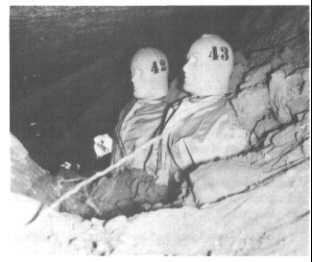
Unsupported earth walls should be sloped as much as practical. The length and strength of available roofing material should be considered and, in order to attain effective earth arching, the thickness of the earth cover should be at least half as great as the distance between the edges of the trench.
The stability of the earth determines the proper method for shoring the walls of a trench, shelter.
Book Page: 247
Methods for shoring both loose, unstable earth and firm, stable earth are described below:
* In loose, unstable earth such as sand, the walls of all underground shelters must be shored. First, an oversized trench must be dug with gently sloping sides. Next, the shoring is built, often as a freestanding, roofless structure. Then earth must be backfilled around the shoring to a level a few inches higher than the uppermost parts of the shoring, as in Fig. D.7. Finally, the roof poles or planks must be placed so that they are supported only by the backfilled earth. Blast tests have indicated that a Pole-Covered Trench Shelter thus proportioned and lightly shored should protect its occupants against disastrous collapse of its walls at overpressure ranges up to 15 psi.
* In firm, stable earth, it is best first to dig a trench a few inches wider than 7 feet (the length of the roof poles) and 1 foot deep. Next, dig the part to be shored, down the center of this shallow trench, using the dimensions given for the shoring in Fig. D.7. The trench walls should be sloped and smoothed quite accurately, so that the shoring can be tightened against the earth. If the shoring does not press tightly against the trench walls, large wedges of earth may be jarred loose, hit the shoring, and cause it to collapse.
A different, comparatively simple way to tighten shoring is indicated by Fig. D.8. This sketch shows a 4-pole frame designed to be installed every 2-1/2 feet along a trench in stable earth and to be tightened against trench-wall shoring with the same dimensions as those shown in Fig. D.7. Note that the two horizontal brace poles have shallow "V" notches sawed in both ends.
Fig. D.7. An illustration of several ways to shore a trench in unstable earth, using various materials. A 4-piece frame (consisting of 4 poles, or 4 boards, installed as shown above) should be installed every 2-1/2 feet along the length of the trench, including the horizontal parts of the entryways. All parts of the shoring should be at least 2 inches below the roof poles, so that the downward forces on the roof will press only on the earth. (ORNL-DWG 78-14430R) 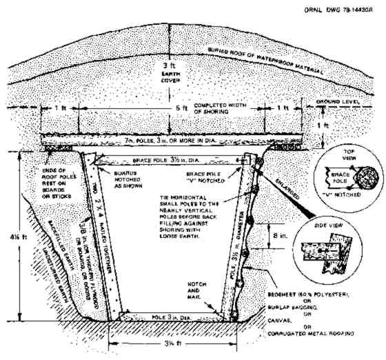
Book Page: 248
Fig. D.8. A 4-pole frame designed so that it can be tightened against the shoring materials that must press firmly against the walls of a trench dug in stable earth. (In this sketch, the middle sections of three poles have been removed, so that the upper brace pole may be seen more clearly.) (ORNL DWG 78-17246R) 
If these brace poles are driven downward when positioned as shown, the two wall poles are forced outward against the shoring materials placed between them and the earth walls. An upper brace pole should be cut to the length needed to make it approximately the same height as the roof poles on each side of it (no higher) after the shoring is tightened. Finally, each "V"-notched end should be nailed to its wall pole.
Light, yielding poles can serve simultaneously both to roof and to shore a shelter. A good example is the Chinese "Man" Shelter illustrated in Fig. D.9, requiring comparatively few poles to build.21 This shelter is too cramped for long occupancy, and its unshored, lower earth walls can be squeezed in by blast pressure. Therefore, it is not recommended if sufficient materials are available for building a well- shored, covered-trench shelter. It is described here primarily to help the reader understand the construction of similarly designed entryways, outlined later in this appendix. The room and the horizontal entryway of the model tested were made of 6-1/2-foot poles averaging only 3 inches in diameter. It had two vertical, triangular entries of ORNL design. Each was protected by an expedient triangular blast door made of poles. In Fig. D.9, note the two small horizontal poles at the top of the triangle, one tied inside and the other tied outside the triangle, to hold the wall poles together. Before covering this shelter with earth, a 6-inch-thick covering of small limbs was placed horizontally across the approximately 3-inch wide spaces between the 6-1/2 foot wall poles; the limbs were then covered with bedsheets.
Fig. D.9. Chinese "Man" Shelter tested at 20 psi, and undamaged because the thin poles yielded and were protected by earth arching. This drawing was taken from a Chinese civil defense manual. The dimensions are in centimeters. 
When blast-tested in loose, unstable soil, the unsupported earth walls of the trench below the wall poles were squeezed in. The 12-inch width of the foot trench was reduced to as little as 4 inches by the short- duration forces produced by 0.2-kiloton blast effects at 50 psi. The much longer duration forces of a megaton explosion would be far more damaging to the shelter at lower overpressure ranges, due to destabilizing and squeezing-in unshored earth at depths many feet below ground level.
Calculations based on blast-test findings indicate that the unsupported earth walls of a shelter are likely to fail if the aboveground maximum overpressure is greater than 5 to 7 psi and this overpressure is caused by an explosion that is a megaton or more.
Book Page: 249

(Most homes would be severely damaged by the 3-psi blast effects from a 1-megaton or larger weapon. This damage would result one mile closer to ground zero of a 1-megaton surface burst than the distance at which the unshored earth walls of some shelters would be collapsed. For a 20-megaton surface burst, the corresponding reduction in distance would be about 2.7 miles.)
° Build sufficiently long and strong entryways. Blast shelters need longer horizontal entryways, taller vertical entryways, and thicker earth cover than do most fallout shelters; these are needed primarily for increased protection against high levels of initial nuclear radiation. The entryways of the Small-Pole Shelter described in Appendix A.3 (with the improvements for increased blast protection outlined in the following section of this appendix) afford protection against both blast and radiation up to the 50-psi overpressure range. However, these entryways require straight poles 14 feet long; these may be difficult to find or transport.
In contrast, both the horizontal and the vertical parts of the triangular entry pictured in Figs. D.10, D.11, and D.12 require only small-diameter, short poles. Triangular entries of this type were undamaged by 1-kiloton blast effects at the 20-psi overpressure range5 and by 0.2-kiloton blast effects at 50 psi. This type of entry and its blast door (also triangular and made of short poles) can be used with a wide variety of expedient blast shelters and should withstand megaton blast effects at 25 psi. Therefore, their construction is described in considerable detail.
* The horizontal part of a triangular entry: if the Chinese Man" Shelter shown in Fig. D.9 is made without excavating the unshored lower trench that forms its earth seats, it will serve as a horizontal, shored crawlway-entry affording blast protection up to at least the 25-psi overpressure range. Two horizontal entries, one at each end of the shelter, should be provided. Each entry should be 10 feet long. This length is needed to reduce the amount of initial nuclear radiation reaching the blast shelter room while assuring adequate through-ventilation. The outer part of such a horizontal entry is pictured in the background of Fig. D.10.
* The vertical part of a triangular entry: The lower section of the vertical part is made in a similar manner to the horizontal shelter shown in Fig. D.9. Figure D.10 shows 4-1/2 foot horizontal poles (1) forming a "V", with one end of each pole laid on top of the adjacent lower pole. The other ends of these poles (1) are pressed against the two pairs of vertical posts (2). (After this photo was taken, the tops of these two pairs of vertical posts were sawed off as shown in Fig. D.11.) The 4-1/2-foot horizontal poles (1) were kept level by the short spacer-poles (3) that were wired or nailed in place.
Fig. D. 10. Uncompleted lower section of a vertical triangular entry. (Photo 2954-77R) 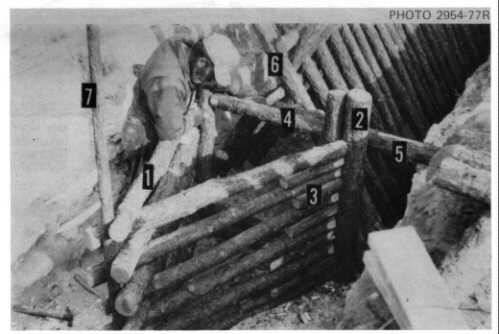
Book Page: 250
Fig. D. 11. Lower part of a vertical triangular entry, showing its connection to the horizontal part of the shelter entry. (ORNL-DWG 78-14675) 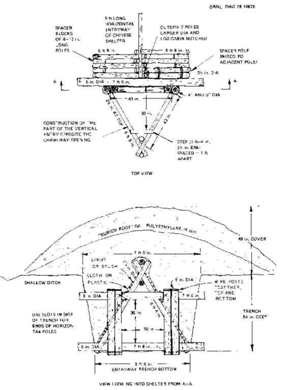
Book Page: 251
Fig. D. 12. Completed frame of Chinese "Man" Shelter showing its two ORNL-designed entryways (one at each end) and triangular blast doors made of poles. Before covering the triangular vertical entries with earth, tree branches were placed vertically over the sides; the branches then were covered with bedsheets. Horizontal branches, also covered with bedsheets, were laid over the rest of the shelter frame. After being covered with earth, this shelter was subjected to 1-kiloton blast effects. Multiple earth arching over and around this yielding structure prevented both the small poles and the bedsheets from being damaged at 20 psi. 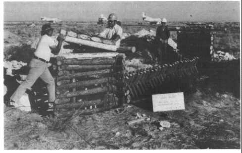
Each pair of vertical posts (2) was securely wired together at top and bottom. The two pairs were held apart at top and bottom by two horizontal brace- poles toenailed in place to frame the rectangular 30- X 30-inch crawlway "doorway" between the vertical entry and the horizontal entry. Only the upper pole (4) of these two 30-inch-long horizontal brace-poles is shown.
The two pairs of vertical posts (2) were positioned so that they pressed against two 7-1/2-foot horizontal poles (5); only the uppermost is shown. These in turn pressed against the outermost two poles (6) of the horizontal entry and against the earth in two slot-trenches dug in the sidewalls of the excavation. These two 7-1/2-foot poles (5) should be at least 6 inches in diameter.
Additional details of the lower section of this vertical triangular entry are given in Fig. D.11. If horizontal poles considerably larger in diameter than those illustrated are used, fewer poles are required and strength is increased. However, the space inside the entry is decreased unless the larger-diameter horizontal poles that form the "V" are made longer than 4-1/2 ft.
As shown on the left in Fig. D.10, a small, vertical pole (7) was placed in the small "V" between the outer ends of the horizontal poles that form the lower section of the vertical entry. After this photo was taken, a second small, vertical pole was positioned in the adjacent large "V", inside the entry. These two poles (7) were then tightly wired together so as to make a strong, somewhat yielding, outer- corner connection of the horizontal poles (1) in the same way that the tops of the side-wall poles of the Chinese "Man" Shelter are bound together.
The upper section ofthe vertical part of this entry (the section above the tops of the two pairs of vertical posts shown in Fig. D.10 and Fig. D.11) is made by overlapping the ends of its nearly horizontal poles (Fig. D.12). These poles [marked with a (1) in Fig. D.10] were each 4 feet 6 inches long and varied uniformly in diameter from about 2-1/2 inches just above the two pairs of wired-together posts, to 4-inch diameters just below the triangular door frame of poles. The triangular-shaped blast door was hinged to and closed against this door frame. The hinges were strips cut from worn auto tires, to be described shortly.
Book Page: 252
The upper section is formed by laying poles in a triangular pattern, ends crossing at the angles, with large ends and small ends placed so that the poles are as nearly horizontal as is practical. Each of its three corners is held together by strong wires that tightly bind an outside and an inside small vertical pole, in the same manner as the top of the Chinese "Man" Shelter (shown in Fig. D.9) is secured. (Instead of No. 9 soft steel wire, rope or twisted strips of strong fabric could be used.)
Before starting to install the upper section of a vertical triangular entry, the three outermost of the six small vertical poles that will hold the three corners together should be connected temporarily with three small horizontal poles. Connect them at the height of the door frame planned for the triangular blast door, and space them so as to be the same size as this door frame.
Next, all the horizontal poles should be laid out on the ground in the order of their increasing diameters. The triangular entry then should be started with the smallest poles at the base, with increasingly large-diameter poles used toward the top so that the three pairs of small vertical poles will press securely against all the horizontal side poles of the entry.
To prevent the negative overpressure ("suction") phase of the blast from yanking out and carrying away the blast door and the upper part of the vertical entry to which it is hinged, the uppermost 4 or 5 horizontal poles of each of the three sides of the vertical entry should be wired or tied securely together. Rope or strips of strong cloth can be used if strong wire is not available.
Before placing earth around this lightly constructed blast-protective entry, the vertical walls must be covered to a thickness of about 6 inches with a yielding, crushable covering of limbs, brush, or innerspring mattresses. Limbs or brush should be placed in three layers, with the innermost layer at right angles to the underlying poles. The yielding thickness then is covered with strong cloth, such as 50% dacron bedsheets, or two thicknesses of 4-mil polyethylene film. This outermost covering keeps loose earth or sand from filling spaces inside the yielding layer or running into the entry. Thus protected, this vertical entry should be undamaged by 25-psi blast effects of megaton weapons.
A vertical blast-protective entry can also be made like a strong box, using 2-inch-thick boards. Such entries afford blast protection up to 50 psi if made as small as shown here and protected with yielding materials such as a 6-inch-thick layer of brush covered with strong cloth.
Fig. Pg. 252 A vertical blast -protective entry. 22 in. x 28 in. 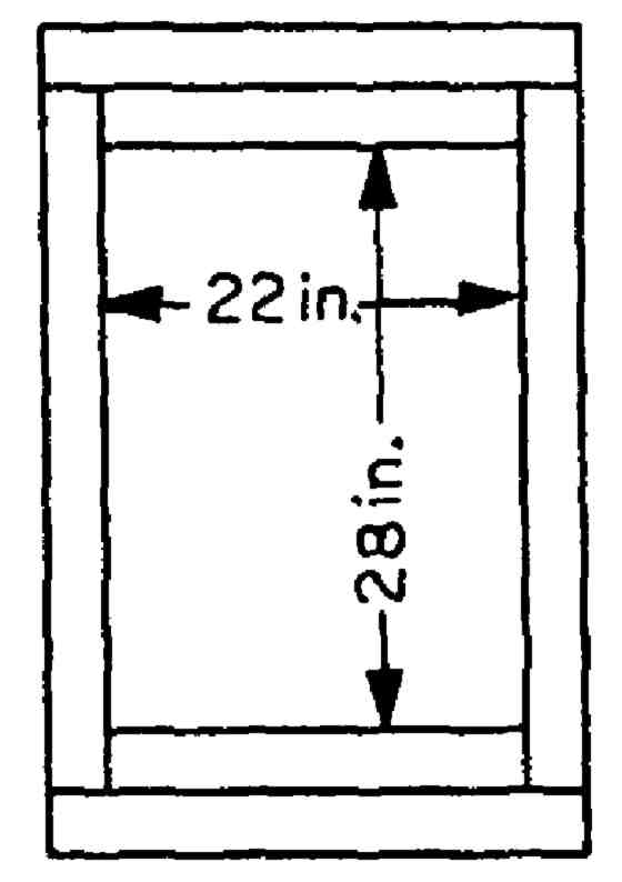
° Install blast doors to keep out airborne blast waves, blast wind, overpressure, blast-borne debris, burning-hot dust and air, and fallout.
A fast-rising overpressure of as little as 5 psi will break some people's eardrums. At overpressures of 15 to 20 psi, 50% of the people who are exposed will have their eardrums broken. However, persons near a shelter wall may have their eardrums broken by somewhat less than half of these unreflected overpressures. (Any wall may reflect blast waves and greatly increase overpressures near it.) Broken eardrums are not serious in normal times, but after a nuclear attack this injury is likely to be far more dangerous to persons in crowded shelters without effective medical treatment. Lung damage, that can result from overpressures as low as 10 to 12 psi, would also be more serious under post-attack conditions.
A blast door must withstand blast waves and overpressure. Not only must the door itself be sufficiently strong to withstand forces at least as great as those which the shelter will survive, but in addition the door frame and the entranceway walls must be equally as strong. The expedient blast door pictured in Fig. D. 13 was made of rough boards, each a full 2 inches thick. It had a continuous row of hinges made of 18-inch-long strips cut from the treads of worn car tires.
Book Page: 253
Fig. D.13. Blast door surrounded by 4 blast-protector logs that were notched and nailed together. The wet, mounded soil had been compacted by the blast but not blown away. 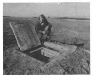
The strips were nailed to the vertical poles on one side of the vertical entry. These and other details of construction are shown in Fig. D. 14. Although the two center boards were badly cracked by the shock wave and overpressure at the 17-psi range, the door pictured in Fig. D.13 afforded good protection against all blast effects from a surface explosion of a million pounds of TNT. In Fig. D.14,note the essential, strong tie-down attachment of the wires at the bottom of the vertical entry, to prevent the blast door from being yanked open by the negative pressure ("suction") that follows the overpressure.
Blast doors must be protected against reflected pressures from blast waves that could strike an edge of an unprotected door and tear it off its hinges. Note the blast-protector logs installed around the door pictured in Fig. D. 14. When the door was closed, the tops of these four logs were about 2 inches higher than the door, thus protecting its edges on all sides.
The closed door must be prevented from rebounding like a spring and opening a fraction of a second after being bowed down by overpressure, or from being opened and perhaps torn off its hinges by the partial vacuum ("suction") that follows the overpressure phase. Figure D. 14 gives the details of such a hold-down system for a blast door. Note that near the bottom of the vertical entry the 6 strong wires must encircle a horizontal pole that is flattened on one side and nailed to the vertical wall poles with at least a dozen 6-inch (60-penny) nails. Blast tests up to the 53-psi overpressure range have proved that this hold-down system works.5
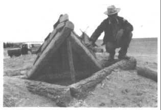
Figure D. 15 shows a blast door made of 5 thicknesses of 3/4-inch exterior plywood, well glued and nailed together with 4-1/2-in. nails at 4-in. spacings. This door was protected by 4 blastprotector logs, each 8 feet long and about 8 inches in diameter. The logs were notched, nailed together, and surrounded with earth. For protection against ignition by the thermal pulse from an explosion, exposed wood and rubber should be coated with thick whitewash (slaked lime) or mud, or covered with aluminum foil.
An equally strong blast door and the door base upon which it closes can be made of poles. If poles are fresh-cut, they are easy to work with ax and saw. Figure D.16 shows the best blast-tested design. This door also had a continuous row of hinges made from worn auto tire treads. The pole to which the hinges were attached was 7 inches in diameter after peeling and had been flattened on its top and outer sides. The two other poles of the equal-sided triangle were 8 inches in diameter and had been flattened with an ax on the bottom, top, and inner sides. The three poles were each 55 inches long. They were notched and spiked together with 60-penny nails so that the door would close snugly on its similarly constructed base made of three stout poles. Other poles, at least 7 inches in diameter before being hewn so that they would fit together snugly, were nailed side-by-side on top of the three outer poles.
Many Americans have axes and would be able to cut poles, but not many know how to use an ax to hew flat, square sides on a pole or log. This easily acquired skill is illustrated by Fig. D.17. The worker should first fasten the pole down by nailing two small poles to it and to other logs on the ground. Figure D.17 shows a pole thus secured. When hewing a flat side, the worker stands with his legs spread far apart, and repeatedly moves his feet so that he can look almost straight down at where his ax head strikes. First, vertical cuts with a sharp ax are made about 3 or 4 inches apart and at angles of about 45 degrees to the surface of the pole, for the length of the pole. These multiple cuts should be made almost as deep as is needed to produce a flat side of the desired width. Then the worker, again beginning at the starting end, should cut off long strips, producing a flat side.
Book Page: 254
Fig. D.14. Expedient blast door that can be closed and secured in 4 seconds. Four seconds would be too little time if the shelter is at the 15-psi overpressure range from a 550-kiloton or smaller warhead - typical of the 1987 Soviet ICBM arsenal. (See the last paragraph on page 255.) However, this door closure is still the best blast-tested expedient means to secure a closed blast door. (ORNL-DWG 73-1063) 
Book Page: 255
Fig. D.15. Tire-strip hinges nailed to an expedient, 4-inch-thick blast door made of plywood, designed to withstand 50-psi blast effects of very large weapons and undamaged by blast at the 53-psi range. Fig. D.16. Blast-tested triangular blast door made of hand-hewn pine poles, notched and nailed together. This door closed on a triangular pole base that is concealed in this photo by two of the three blast-protector logs that also withstood 53-psi blast effects. Fig. D.17. Hewing flat sides on a pole with a sharp ax. 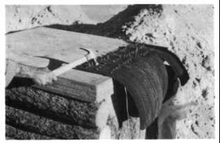

To hew a second flat side at right angles to the first side, rotate the pole 900, secure it again, and repeat as pictured in Fig. D.17.
° Provide blast closures for an adequate ventilation system. The following two expedient closure systems permit adequate volumes of ventilating air to be pumped through a shelter:
1. Install two blast doors, one on each end of the shelter, designed to be left open until the extremely bright light from a large blast is seen. Figure D. 14 shows a door held open by a prop-stick that can be yanked away by the attached pull-cord. While propped open, one blast door serves as an extremely low-resistance air-intake opening, and the other serves as an air-exhaust opening. A large KAP can pump air at the rate of several thousand cubic feet per minute through such open doors.
When an attack is expected, each pull-cord should be held by a shelter occupant who stays ready at all times to yank out the prop-stick as soon as he sees the light of an explosion. After the door has fallen closed, the loop at the end of its wire bridle is close to the upper hook of the load-binder and at the same height (Fig. D.14). The person who closes the door should quickly hook the upper hook of the load- binder into the wire loop and pull down on the handle of the load-binder. The door will then be tightly shut. (Sources during an emergency would be the millions of load-binders owned by truckers and farmers.)
At distances from a large explosion where blast wave and overpressure effects are not destructive enough to smash most good expedient blast shelters, there is enough time between the instant the light of the explosion is seen and the arrival of its blast wave for an alert person to shut and securely fasten a well- designed blast door. The smaller the explosion and the greater the overpressure range, the shorter the warning time. Thus at the 15-psi overpressure range from a 1-megaton surface burst (1.5 miles), the blast wave arrives about 2.8 seconds after the light; whereas at the 10-psi overpressure range from a 1- megaton surface burst (1.9 miles), the blast wave arrives about 4.5 seconds after the light. For a 20- megaton surface burst, the warning time at the 15-psi range is about 8 seconds, and at the 30-psi over- pressure range, about 4 seconds. Experiments have shown that even people who react quite slowly can close and secure this door within 4 seconds after seeing a spotlight shine on the door without warning.
Book Page: 256
2. Build a vertical air shaft next to the outermost side of each vertical entry, with an Overlapping-Flaps Blast Valve (see Fig. D. 18) connecting each entry to its air shaft, as shown in Fig. D. 19. These air shafts and blast valves permit forced ventilation to be maintained when the two blast doors are closed. Figure D. 18 illustrates the construction of a fast-closing expedient blast valve, a design that was undamaged by the 65-psi shock wave and other effects produced by the explosion of a million pounds of TNT. When blast-tested in a shock- tube at 100-psi, the flaps were undamaged; they closed in 6/1000 of a second (0.006 sec.). This is as fast as the best factory-made blast valves close.
Fig. D.18. Overlapping-Flaps Blast Valve, made of boards, plywood, and strips cut from the treads of worn car tires. (ORNL DWG 73-2229A) 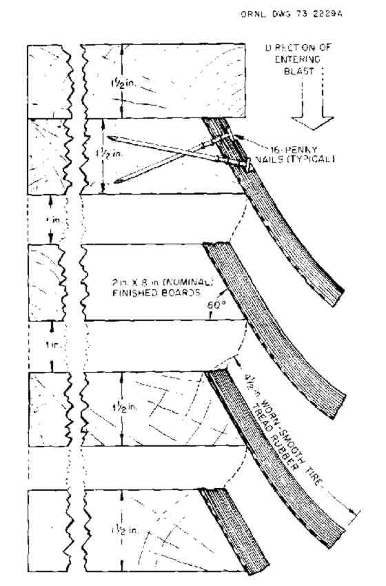
To withstand 50 psi, the load-bearing "2-inch" boards (actually 1-1/2inches thick) of the valve should be at least 6 inches wide, if the 1-in.-high air openings are each made 12 in. wide, measured between two vertical poles of a shelter entry. See Fig. D.19, that gives the dimensions of a valve that has been blast tested.5 Note that there are 5 inches of solid wood at each end of each 1-in.-high air opening. If there are 5 such air openings to a valve, a properly installed KAP (Appendix B) can pump air at about 125 cubic feet per minute (125 cfm) through a shelter equipped with such valves. This ventilation rate is ample for at least 40 people in cold weather. Except in hot and humid weather, a constant air supply of about 10 cfm per shelter occupant is enough to maintain tolerable conditions during continuous shelter occupancy for many days.
Fig. D.19. Installation of a 50-psi Overlapping- Flaps Blast Valve in such a way that it will not be blown into a shelter by the blast overpressure, nor pulled out by the following negative pressure ("suction") phase. (ORNL-DWG 78-14429R) 
If a factory-made blower capable of pumping more than 100 cfm is available, use it. Such a hand- operated blower can pump against much higher air flow resistances than a KAP can. It can pump its full-rated volume of outdoor air through a shelter equipped with two Overlapping-Flaps Blast Valves, one at each end of the shelter and each with only 2 air openings-providing a total of 24 square inches of openings per valve. Equally or more effective is a homemakeable Plywood Double- Action Piston Pump, made and operated as described in Appendix E.
Book Page: 257
Remember that a pressure of 7200 pounds pushes against each square foot of the exposed face of a blast valve when it is subjected to a 50-psi blast overpressure. Also keep in mind that the "suction" that follows can exert an outwardly directed force of up to 700 pounds per square foot on the valve face and can yank it out of position unless it is securely installed. Figure D. 19 shows how to securely install a blast valve. (Merely nailing a blast valve in its opening will not enable it to withstand severe blast forces.)
Note in Figure D.19 that an opening is shown between the back edge of the uppermost board of the Overlapping-Flaps Blast Valve and the adjacent horizontal pole of the vertical entry. Both this opening and the similar opening next to the lowermost board of the Blast Valve should be closed off with a stout board, to prevent blast from going through these openings and on into a vertical entry and the shelter room.
The top of an air shaft should be a few inches higher than the earth piled around it, as are the tops of the vertical entries of the Small-Pole Shelter illustrated in Figure A.3.1 on page 174. To minimize the amount of rain that may fall into an air shaft, a shed-like, open-sided miniature roof should be placed over it, a few inches above its top. The roof can be lightly constructed, since it will be blown away by a severe blast.
° Minimize aboveground construction and the mounding of shielding earth. At high overpressure ranges, the shock wave and the blast-wind drag can wreck an aboveground shelter entry. For example, the 5-ft-high earth mound over a shelter built with its pole roof at ground level was moved enough by 1-kiloton air-blast effects at the 53-psi overpressure range to break one of the poles of a blast-door frame. The forces of a 1-megaton explosion at the same overpressure range would have operated 10 times as long, and probably would have smashed the vertical entryways of this shelter. Whenever practical, a blast shelter should be built far enough belowground so that the top of its shielding earth cover is at ground level. Avoiding above- ground construction and earth mounds also greatly reduces the chances of damage from blast-hurled, heavy debris, such as tree trunks and pieces of buildings.
Dry earth, steeply mounded over a shelter which is subjected to blast winds from a big explosion, will be mostly blown away. However, blast-wind "scouring" of wet earth is negligible. The blast winds from a 1-kiloton explosion at the 31-psi overpressure range scoured away 17 inches of dry, sandy soil mounded at a slope of 32 degrees.
If it is impractical to build a blast shelter with its roof belowground, good projection can be attained by mounding even dry earth at slopes not steeper than 10 degrees.
° Provide adequate shielding against initial nuclear radiation. Good expedient blast shelters require a greater thickness of earth cover than is needed on good fallout shelters, for these reasons:
* Blast shelters should also protect against initial nuclear radiation emitted by the fireball. This radiation is reduced by half when it penetrates about 5 inches of packed earth (as compared to a halving-thickness of only about 3-1/2 inches of earth against radiation from fallout).
* The initial radiation, in some areas where good blast shelters will survive, can be much greater than the fallout radiation is likely to be.
* Initial nuclear radiation that comes through entryways is more difficult to attenuate (reduce) than fallout radiation. Therefore, longer entry- ways or additional right-angle turns must be provided.
For these reasons, good blast shelters should be covered with at least 4 ft of well-packed, average-weight earth, or 5 ft of unpacked or light earth. (A 3-ft thickness gives excellent protection against radiation from fallout.)
A 50-PSI SMALL-POLE SHELTER
This expedient blast shelter is described in detail to enable the reader to build this model. The details will help him better understand the design principles of other expedient blast shelters that are capable of preventing injuries from blast effects severe enough to destroy all ordinary buildings and kill the occupants. Blast tests and calculations have indicated that the Small-Pole Shelter described and illustrated in Appendix A.3 will afford protection against all weapon effects at overpressure ranges up to 50 psi that are produced by an explosion of 1 megaton, or larger, provided the shelter is:
° Made with horizontal entryways each with ceilings no higher than 7 ft, 2 in., no wider than 3 ft, and each at least 10 ft long to lessen the radiation coming through the entries (see Fig. D.20). Lower and narrower entryways would give better protection but would increase the time required for entry.
° Constructed with a floor of poles that are 4 in. or more in diameter, laid side-by-side, with the wall poles resting on the floor poles. The ground shock and earth pressures at a depth of 10 ft or more resulting from an overpressure on the surface of more than about 35 psi, if caused by a large explosion, may destabilize and squeeze earth upward into the shelter through an unprotected earth floor. The Small-Pole Shelter described in Appendix A.3 has an earth floor.
° Installed in an excavation about 13 feet deep, with the shelter's vertical entrances appropriately increased in height so that the blast doors are only about one foot above the original ground level.
To prevent possibly life-endangering cave- in of the 13-foot-deep trench that was dug for the blast testing of this model shelter, the trench walls were sloped about 45 degrees. The shelter was built as a braced, free-standing structure, and then covered. During a crisis it would be impractical to safely excavate a deep trench with steeply sloping walls and then safely build a shelter in it. A 13-foot-deep trench is usually too deep to dig by hand-especially since to dig it with safely sloping walls requires the removal of a large amount of earth.
Book Page: 258
ORNL-DWG 78-18835
Fig. D.20. Entryway of Small-Pole Blast Shelter shielded against initial nuclear radiation. This sketch is a simplified vertical section through the centerline of one end of the shelter. 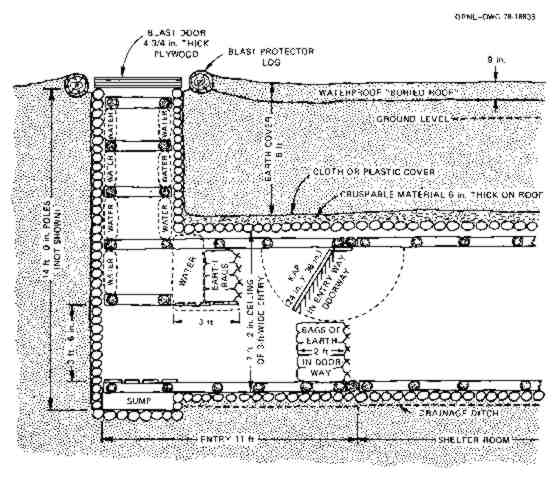
° Made with 4 rectangular horizontal braces in each vertical entry, in addition to the ends of the two long, ladder-like braces. The detailed drawings in Appendix A show' such braces. The lowest rectangular brace should be positioned 3-1/2 feet above the flooring at the bottom of the vertical entry (see Fig. D.20).
° Equipped with blast doors each made of 5 sheets of 3/4-inch exterior plywood (see Fig. D.15) bonded with resin glue and nailed together with 4-1/2 in. nails. The nails should be driven on 4-in. spacings and their protruding ends should be clinched (bent over). The blast doors must be secured against being yanked open by negative pressure ("suction") by securing them with a strong wire bridle (see Fig.-D.14), and with the lower, fixed wire strongly connected near the bottom of the entry to all of the vertical poles on one side, as shown in Fig. D.14.
° Provided with an adequate ventilation pump and with ventilation openings protected against blast by expedient blast-valves (Fig. D.18) installed in the vertical entries as shown in Fig. D. 19, to protect the air-intake and the air-exhaust openings. (Ventilation openings should be as far as practical from buildings and combustible materials. Manually closed ventilation openings are NOT effective at the 50-psi overpressure range of most weapons, because there is insufficient time to close them between the arrival of the warning light from the explosion and the arrival of the blast wave.)
Book Page: 259

° Made with the roof poles covered by a yielding layer of brush or limbs about 6 inches thick, or of innerspring mattresses. This yielding layer in turn should be covered with bedsheets or other strong cloth, to increase the effectiveness of protective earth arching. Brush or limbs should be laid in 3 layers with sticks of the middle layer perpendicular to those of the other two layers.
° Covered with 5 feet of earth, sloped no steeper than 10 degrees.
° Provided with additional shielding materials in the entryways, as shown in Fig. D.20. Such shielding would be needed to prevent occupants from receiving possibly incapacitating or fatal doses of initial nuclear radiation through the entryways at the 50-psi overpressure range, if the shelter is subjected to the effects of a weapon that is one megaton, or larger, in explosive yield.
Damp earth serves better for neutron shielding material than dry earth and can be substituted for water as shielding material if sufficient water containers are not available. (At the 50-psi over- pressure range from explosions smaller than one megaton, the entry and shielding shown in Fig. D.20 may not provide adequate protection against initial nuclear radiation.)
When the shelter is readied for rapid occupancy, the shelter-ventilating KAP is secured against the ceiling, and the bags of earth in the doorway (under the KAP) are removed. Persons entering the shelter would stoop to go under the platform adjacent to the vertical entry. This platform is attached to vertical wall-poles of the horizontal entry and supports shielding water and earth. When all except the person who will shut and secure the blast door are inside the shelter room, occupants should quickly begin to place bags of earth in the doorway. When the attack has begun, the whole doorway can be closed with bags of earth or other dense objects until ventilation is necessary.
The entries of other types of blast shelters can be shielded in similar ways.
° Protected against fire by being built sufficiently distant from buildings and flammable vegetation and by having its exposed wood covered. For maximum expedient protection against ignition by the thermal radiation from a large explosion, all exposed wood should be free of bark, coated with wet mud or damp slaked lime (whitewash), and covered with aluminum sheet metal or foil to reflect heat. (Most of the thermal radiation from an explosion that was 1 megaton or larger would reach the 50-psi over- pressure range after the blast wave had arrived and had torn the expedient protective coverings from the wood. However, as has been observed in megaton nuclear weapon tests, the dust cloud first produced by the popcorning effect and later by the blast winds would screen solid wood near the ground so effectively against thermal radiation that it would not be ignited, provided it had been initially protected as described above.)
PRECAUTIONS FOR OCCUPANTS OF BLAST SHELTERS
Although a well constructed blast shelter may be undamaged at quite high overpressure ranges, its occupants may be injured or killed as a result of rapid ground motions that move the whole shelter several inches in a few thousandths of a second. Rapid ground motions are not likely to cause serious injuries unless the shelter is in an area subjected to 30- psi or greater blast effects. To prevent possible injury, when the occupants of high-protection blast shelters are expecting attack they should avoid:
° Having their heads close to the ceiling. The 'air slap" of the air-blast wave may push down the earth and an undamaged shelter much more rapidly than a person can fall. If one's head were to be only a few inches from the ceiling, a fractured skull could result.
° Leaning against a wall, because it may move very rapidly, horizontally as well as vertically.
° Sitting or standing on the floor, because ground shock may cause the whole shelter (including the floor) to rise very fast and injure persons sitting or standing on the floor. The safest thing to do is to sit or lie in a securely suspended, strong hammock or chair, or on thick foam rubber such as that of a mattress, or on a pile of small branches.
In dry areas or in a dry expedient shelter, ground shock may produce choking dust. Therefore, shelter occupants should be prepared to cover their faces with towels or other cloth, or put on a mask. If an attack is expected, they should keep such protective items within easy reach.
Book Page: 261
| |
|
Straight FAQ's on FEMA Surplus Civil Defense Meters with Retail and Wholesale Sources Listed! |
|
for Potassium Iodide (KI) tablets, Potasium Iodate (KIO3) pills, and all forms of protective iodine! |